
Introduction to Fluid Mechanics
Contents
1. Introduction to Fluid Mechanics#
Fluid flows play a hugely important role in a wide range of problems in science and engineering, from the flow of water through a pipe, blood through a vein or artery or the hugely complex atmospheric dynamics that govern our climate. Understanding how fluids behave and evolve is a complex, yet highly important area of engineering, enabling us to tackle problems from building pumps to designing supersonic aircraft.
The motion of a fluid – either a liquid, or a gas – is inherently complex, and in many cases appears random, which makes it both hard to predict and difficult to analyse. Understanding fluid dynamics has proven to be one of the most important and exhaustively studied problems in mathematics, physics and engineering, spanning more than two centuries of detailed investigation.
In this section, we will outline some of the basic properties of fluids, describe the key forces that act upon them, and outline the mathematical framework in which we can study fluid dynamics.
1.1. What is a fluid?#
Broadly speaking, as humans we can intuitively define what a fluid is and somehow distinguish it from a solid. If we were to try and summarise this, probably most people would say that a fluid flows in some manner. For example, there is a clear motion of a fluid when filling a container like a bath, which we can visualise very easily by observing the fluid’s motion from a tap, or by putting things into the bath – the ubiquitous rubber duck, for example! Likewise, when that source of disturbance is removed, the fluid will eventually come to rest and remain still. However this intuitive definition is clearly lacking for any sort of technical reasoning: what is the key distinction between a fluid and a solid?
We can answer this question by observing the response of some material to an external force. Let’s assume we have a container full of fluid – specifically a liquid – next to a solid which we’ll apply a force \(F\) to in various directions. Before our experiment, here’s our setup:

Fig. 1.1 A fluid sits in a container on the left hand side, and a solid on the right hand side.#
Now let’s apply a small uniform force \(F\) in a direction perpendicular to the surface – in the case of the fluid, via use of e.g. a piston. What happens to each material? Our experiment might now look something like the below:

Fig. 1.2 An axial force \(F\) is applied to both the fluid and the solid, resulting in the deformation of the solid but not the fluid.#
The solid will likely observe a small deformation both laterally with a change of length \(\Delta L\) (and likely laterally as well, according to the Poisson ratio of the material), depending on the force applied and the material’s properties, but will eventually reach a static state where it has been compressed and eventually resists the force. (This is essentially the content you have been learning in the second year materials module.) Likewise, the fluid will generally behave in a similar manner, depending on whether it is a liquid or a gas:
Liquids are incompressible, meaning that the volume that they occupy does not change when they are subject to an external force: i.e. the density \(\rho\) remains constant, because the mass and the volume of fluid within our container both remain constant. Incompressible fluids often power many important engineering applications, such as hydraulic pumps.
Gases on the other hand are compressible, meaning that in response to our force they would compress to occupy a smaller volume. The mass of the gas within our container clearly remains unchanged, but now that it occupies a smaller volume its density has changed.
For the most part, in the first part of this course we will only be considering incompressible fluids, i.e. liquids. Later when we consider thermodynamics, we will consider compressible fluids.
Warning
Note that in practice, no liquid is truly incompressible, but they have far greater resistance to compression than gases.
Now instead, let’s consider a force that is applied tangentially to the material: a shear force. In this case, the behaviour of the fluid and the solid is much different:

Fig. 1.3 Now a shear force \(F\) is applied to both the fluid and the solid, resulting in the flow of the fluid owing to a lack of resistance, and a small deformation to the solid since the force is absorbed.#
The solid absorbs the force \(F\) and comes to rest. The fluid, on the other hand, cannot absorb the force: instead the top of the fluid starts to move with a velocity \(v\). This then, is the distinction between a fluid and a solid: fluids continually deform: or in other words, they flow under the action of a shear force.
It is important to note that it is not true that the fluid will continue to accelerate indefinitely under the action of \(F\), or that it offers no resistance to a shear force. For example, if you stir a cup of tea and withdraw the spoon, eventually the fluid will naturally come to rest instead of spinning indefinitely! This is because fluids offer resistance to shear forces via friction, rather than via elasticity as would be the case in a solid.
1.2. The continuum description of a fluid#
The mechanics you have studied to date has been based around point masses and classifying the action of forces on them. This is a simple yet powerful approach, which allows us to model relatively complex static systems, such as the trusses on a bridge, and dynamic systems as well such as the motion of a projectile through the air. However, in simplifying the model in this manner, we have neglected the dimensions of the problem, since each point source is naturally a zero-dimensional representation.
Conceptually at least, we could move to studying fluid dynamics in this manner: each molecule of fluid can be modelled as a point, and we can then use knowledge from particle physics to characterise the forces between each molecule. Combined together with Newton’s laws of motion that you are already familiar with, this approach would theoretically give the ability to study the dynamics of a fluid – indeed this molecular dynamics approach is an important area of study in science and engineering, particularly in for example the study of materials. However to do so for any sort of practical problem would be completely intractible: a litre of water contains around around \(3.4\times 10^{25}\) molecules of \(H_2O\)! Besides this, modelling physics on the microscopic spatial and time-scales of individual particles is far removed from the reality that we encounter in everyday macroscopic life.
1.2.1. The continuum assumption#
It is clear that we therefore require an alternative approach, and one in which we can ignore the effects of individual particles. To do so, we can assume that a given fluid is made from an infinite number of volume elements, each of which is “infinitessimally” small. Inside each of these elements, we assume that the observable properties of the fluid, such as its density, velocity, temperature and pressure remain constant.
But how does this process actually work? A good example is to think about calculations of density. Given a mass \(m\) and a volume \(V\), we are very used to calculating the density \(\rho\) as
However, this makes an implicit assumption that the material in question is entirely homogeneous, which in reality is essentially impossible. For example, any given material will naturally possess many imperfections at both the macroscopic level that is visible to the human eye, and the microscopic level which is not. This calculation then gives us the average density of a given body.
If we instead consider a smaller volume \(\delta V\) contained within the body of a mass \(\delta m\), then its average density is equivalently given by
Taking smaller and smaller volumes, we can get closer and closer to a homogeneous mass within the volume. The question is: how small do we need to go? At some point, our volumes become so small that they encompass only a single molecule, which as we have stated is already too small. If our volume size is too large, then the material properties will not be homogeneous. The continuum assumption is therefore that there is a happy middle ground: some length scale that is small enough that the material’s properties are homogeneous within the volume, but not so small as to be governed by molecular effects. Diagramatically, this might look something like the figure below if we could measure density \(\rho\) as a variable of the volume size \(\delta V\):

Fig. 1.4 Conceptual view of density \(\rho\) as a function of volume size \(\delta V\). At very small volume sizes, microscopic moleular effects dominate the variation in density, and at very large volume sizes macroscopic effects cause non-uniform variations. However in the middle lies a region with homogeneous density, which is the continuum assumption.#
It turns out that this is actually not an unreasonable assumption, and indeed for most applications will give very accurate predictions of not only fluid dynamics, but other areas such as structures and materials. This approach also allows us to leverage the powerful toolbox of calculus to bring to bear on fluids, since the process of taking a ‘smaller and smaller’ volume can be thought of as adopting a mathematical limit, i.e.
Although this lies somewhat at odds with the concept that that \(\delta V\) is ‘sufficiently small’, it transpires that this approximation is not only mathematically useful, but highly accurate in practice for most fluid dynamics problems.
1.3. A mathematical framework#
Adopting a continuum framework for fluid dynamics means that we can define a robust mathematical framework in which to study fluids, by disregarding individual particles in favour of a continuum of space that represents the body. Material properties on the body can therefore be represented by mathematical functions on that space. For example, if space is represented in Cartesian space \((x,y,z)\), then the density \(\rho\) is represented by a function \(\rho(x,y,z)\):

Fig. 1.5 The scalar density field \(\rho(x,y)\) defined at each point in the Cartesian plane.#
Since density at a given point is a number, \(\rho\) is a scalar function: given a position in space, it returns the density at that point.
1.3.1. Velocity fields#
In classical mechanics, you might have studied projectiles that move with a given direction and speed: in other words, its velocity. In three-dimensions, this is represented by a typically time-dependent velocity vector \(\vec{u}(t)\), which we might write as
where \(\hat{i}\), \(\hat{j}\) and \(\hat{k}\) represent the standard unit vectors and \(u\), \(v\) and \(w\) denote velocity in the \(x\), \(y\) and \(z\) coordinate respectively.
One of the most important quantities in fluid dynamics is the extension of this concept, so that now \(\vec{v}\) is defined not only for a single point source, but just as in the density vector is defined on the continuum space. Mathematically we could write
or
For brevity however we typically omit the parameters for the velocity, giving e.g. \(\vec{u} = u\hat{i} + v\hat{j} + w\hat{k}\). Diagramatically in two dimensions, this might look something like the below at a single point:

Fig. 1.6 The vector velocity field \(\vec{u}(x,y) = u(x,y)\hat{i} + v(x,y)\hat{j}\) defined at a point in the Cartesian plane.#
However it is worth noting that, in general, the velocity field is given at every point in the domain.
Example: Rotating velocity field
Let us consider the velocity field \(\vec{u}(x,y,t) = -y\hat{i} + x\hat{j}\) in two dimensions. This is an example of a steady velocity field, since the flow changes with position, but not with time. For each point \((x,y)\), we can draw a vector pointing in the direction of \(\vec{u}\), which gives us a plot similar to the one below:

Fig. 1.7 Visualisation of the velocity field \(\vec{u} = -y\hat{i} + x\hat{j}\).#
1.3.2. Steady, unsteady and uniform flows#
In the example above, we have seen that \(\vec{u}\) remains constant at any given time \(t\). Such a fluid is defined to be steady, since its properties do not change in time. In this case this is indicated by omitting \(t\) from the definition of \(\vec{u}\), i.e. the velocity is defined as \(\vec{u}(x,y,z)\). If instead \(\vec{u}\) changes with time, then we denote this by adding \(t\) to the parameters so that \(\vec{u} = \vec{u}(x,y,z,t)\). In this case the fluid is said to be unsteady.
Important
Note that just because a fluid is steady does not mean that it is at rest. Instead think of this as being something that appears ‘frozen’ to your eye. The classical example of this is running a tap: at lower flow speeds, the water appears transparent and steady; as the speed increases it becomes unsteady and meanders. This is also an example of different states of fluid, namely laminar vs. turbulent flow, which we will talk about in the coming lectures.
It is worth noting that steady fluids can also adopt more complex structures, as the video below demonstrates.
For any practical engineering problem, the fluid velocity will generally be three-dimensional. However in some cases, a velocity field might not vary in certain directions, which allows us to make simplifications to the problem at hand and gain further analytic insight. This will be particularly useful for some of the flows we consider in this course. The example below motivates visualisations of these velocity profiles and defines uniform flows.
Example: Channel flow
Some of the most important fluid dynamics problems within engineering are those that are conceptually simple, such as the flow through a pipe or channel. We can imagine that the channel has a wall at the line \(y=-L\), a wall at the line \(y=L\) (so that its height is \(2L\)) and extends into the page in the \(z\)-direction.

Fig. 1.8 Basic setup of a channel flow with walls at \(y=-L, L\).#
Reasonable assumptions for this channel flow are that:
the fluid is steady;
if the channel is sufficiently deep then the fluid velocity will be the same in any \(x-y\) cross-section of the channel;
since the walls are straight, the fluid velocity will not vary in the \(x\) direction.
In this case then, the fluid’s \(v\) and \(w\) components will be zero, which means that our velocity field \(\vec{u}\) has a component of velocity only in the \(x\)-direction, and that component only varies in the \(y\)-direction; i.e. \(\vec{u} = \vec{u}(y) = u(y)\hat{i}\). This is called the velocity profile.
Moreover, let’s also neglect the effect of the walls, and assume that the velocity is given by simply a constant so that \(u(y) = U\). In this case the velocity is said to be uniform, since it is constant in both space and time. This is visualised in the figure below.

Fig. 1.9 A uniform ‘plug’ velocity profile \(u(y)\) showing fluid flow in a channel.#
However, in reality, the walls do have an effect on the flow, as we’ll see below. Later in the course, using the simplifications above, we’ll be able to show that the fluid’s velocity obeys a parabolic profile of the form:

Fig. 1.10 A steady velocity profile \(u(y)\) showing fluid flow in a channel.#
1.4. Streamlines, streaklines and pathlines#
As we’ve seen above, one way of visualising a vector field is simply to take a bunch of points within the domain of interest and draw arrows corresponding to \(\vec{u}\) at each point. However this can be quite time consuming: a better way to visualise the flow field is through the use of streamlines and pathlines.
A streamline is a line that, at a given moment in time, is tangent to all points of the velocity field.
A pathline is a line that traces the path of a particle as the flow evolves in time.
A streakline is the line given if particles are passed continuously through a single spatial point in the field.
To try to conceptualise this:
A streamline is basically a snapshot of the fluid at any given moment in time and is visually similar to e.g. the isobars of pressure you might see on a weather forecast.
A pathline is like dropping a stick in a river and watching the path it makes as it travels downstream.
If you inject dye continuously into a moving fluid at a single point in space, the streak of dye that you will observe is a streakline.
Note
According to the definition above, if the flow is steady, then the streamlines, streaklines and pathlines of the flow will coincide.
An example in a moving velocity field is given below. In the figure:
the arrows indicate the direction of the velocity field;
the dashed lines are the streamlines, which are always tangent to the field;
the red line is a pathline created by a single particle starting at the origin;
the blue line is the streakline generated by continuously injecting particles at the origin.
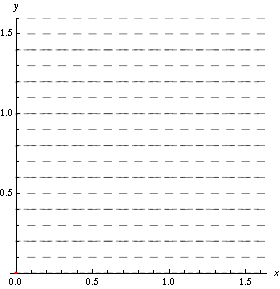
Fig. 1.11 Simulation visualising streamlines and a streakline and pathline from particle(s) injected at the origin. Source: Wikipedia#
.gif)
In the sections below, we will outline how to calculate streamlines and pathlines; the calculation of streaklines however is typically far harder and beyond scope of this course.
1.4.1. Calculating streamlines#
Let us consider how to calculate the streamlines of a velocity field in two dimensions. If we know that a streamline has to be tangent to the velocity field, then we can express this mathematically as
We can at least attempt to solve this equation by recognising that this is a separable ordinary differential equation, which you will have seen before. We can therefore attempt to solve this by moving terms with \(x\) and \(y\) onto the left- and right-hand side of the equation, perhaps as:
In three dimensions this generalises to
This may, or may not, be analytically solveable, depending on \(u\) and \(v\). However for any examples you will see in this course, you can assume that this would be given in a manner that is easy to solve!
Example: Streamlines of a uniform velocity field
Let’s consider a simple, uniform velocity field defined by the constant velocity
Then collecting terms appropriately we have that
where \(c\) is the arbitrary constant of integration. If we choose different values of \(c\), then we can obtain different streamlines. In this case then, we can see that each streamline is simply a straight line – easily deducible for this simple example, but for more complex examples this can be a helpful way to visualise individual “streams” within the flow.
Important
An important property of streamlines is that they cannot cross each other. If they did so, then this would mean that at points where the lines intersected, the velocity would have more than one value – something that is not mathematically permissible!
1.4.2. Calculating pathlines#
To calculate pathlines, we need a similar mathematical framework as in our streamline example. Let us consider a particle that starts at a position \((x_0, y_0)\), and then traces out a path given by the vector \(\vec{r}(t) = (x(t), y(t))\). Mathematically then, we know that the tangent of \(\vec{r}\) will align with the velocity field \(\vec{u}\) at a given moment in time, or in other words that:
In component form this leads to the two ordinary differential equations
with the initial condition that \(x(0) = x_0\) and \(y(0) = y_0\).
Example: Calculating pathlines
Consider the velocity field given by \(\vec{u} = \sin t\, \hat{i} + \hat{j}\). Let’s compute the pathline for a particle starting at the origin, so that \((x_0, y_0) = (0,0)\). Solving the ODE for \(x\) gives
Since we know that \(x(0) = 0\), this implies that \(c = 1\) so that \(x(t) = 1-\cos t\). Similarly the ODE for \(y(t)\) gives
Then since \(y(0) = 0\), \(c = 0\) and we have that \(y(t) = t\). This then gives us a parametric form for \(\vec{r}(t) = (1-\cos(t), t)\). To put this in a standard functional form we need to eliminate \(t\); this is straightforward since we know that \(t = y\), and thus \(x = 1 - \cos y\).
1.5. Fluid forces#
In transitioning from ‘traditional’ mechanics to continuum mechanics, we have outlined in quite some detail the quantities of interest and how these are mathematically represented on a continuum vs. on a point mass. However, we have not yet touched upon the forces that fluids experience, which we need to understand to complete our initial overview of fluid mechanics.
The main forces that appear in ‘standard’ fluid dynamics problems are those due to:
Pressure: a normal, compressive force at a point in space, represented by a scalar function \(p(x,y,z,t)\), which is always present.
Gravity: is always present, but can be neglected when small compared to other forces.
Viscosity: the internal resistive force due to the ‘thickness’ of the fluid. This can also sometimes be neglected when small compared to other forces (although can be dangerous to do so sometimes as we shall learn later!)
Surface tension: when the fluid problem involves multiple kinds of fluids (e.g. air and water), surface tension effects must be considered. You are probably aware of this through the formation of bubbles, or in chemistry when trying to measure the level of a fluid and accounting for the meniscus effect.
In this course, we will consider pressure, gravity and viscosity, but surface tension effects will not be considered. For each of these forces, we will consider the effects of the force on a fluid element \(\delta V\), which we might consider as a small cube, and on its faces of area \(\delta A\).

Fig. 1.12 A sample volume element \(\delta V\) with face area \(\delta A\).#
1.5.1. Gravity#
Fluid forces due to gravity are an example of a body force. As the name suggests, these act on the entire body of the volume, and are proportional to the volume of the fluid element. They act on an element when the body is subject to an external field such as gravity, but other such examples might arise from forces to due e.g. electromagnetic fields.

Fig. 1.13 A sample volume element \(\delta V\) with a gravity force of \(F_g\).#
Mathematically, we can consider a body force as a force per unit volume. For gravitational forces, we know that at some point \((x,y,z)\) that relates to the position of our volume \(\delta V\), the element should experience a force of magnitude \(\rho(x,y,z) g\), where \(g\) is the acceleration due to gravity. We therefore have that the body force due to gravity acting on the element is
If we summed up all contributions from every element – via integration – then we can compute the body force for the entire body.
1.5.2. Pressure#
We know from basic mechanics that pressure is a measurement of force per unit area. In terms of fluid dynamics, the pressure is an example of a surface force on our volume element, and is related to the molecular forces that act upon the volume element’s surfaces.
In the same way that we consider body forces per unit volume, surface forces are taken per unit area. We also consider two types of surface forces; those that are perpendicular to the surface, which we call normal forces, and those which are tangential to the surface, called shear forces.
Fluid pressure is is a normal force which is always compressive, as shown in the figure below. We know from basic mechanics that the force due to a pressure \(p\) on a given surface of area \(A\) is \(pA\). Pressure is measured in SI units as Pascals, where \(1\,\mathrm{Pa} = 1 \,\mathrm{N}\mathrm{m}^{-2}\). Moreover, pressure forces are always equal in all directions around a given volume element.

Fig. 1.14 Pressure force \(F_p\) acting uniformly on a fluid element with surface area \(A\) on each face.#
1.5.3. Viscosity#
Finally, we consider the effect of viscous forces. These are naturally conceptualised as the ‘thickness’ of a fluid, where intuitively we expect substances such as treacle or honey to possess a higher viscosity than water or air. Viscosity is a sort of internal friction within the fluid, where substances with higher levels of viscosity are more resistant to flowing than those with lower levels. The visualisation below shows this:
Fig. 1.15 Simulations of a fluid with a lower viscosity (left) vs. a higher viscosity (right). Source: Wikipedia#
From a molecular perspective, this is explained through increased intermolecular forces between molecules in fluids with higher viscosities. However, from the continuum mechanics perspective, we do not have this concept to fall back on. Instead, we describe viscosity as a shear force between volume elements.
At the start of this section, we described that fluids flow under the action of a shear force, but do not accelerate indefinitely: the viscous force between layers of volume elements is precisely that which will prevent this. In particular, if an external force is being applied and this balances the viscous force, this would lead to a steady flow. Once the external force is removed, then eventually viscous forces will bring the fluid to rest, where the energy of the fluid is dissipated through friction to heat.
Mathematically, however, how do we characterise the viscosity of a fluid and the force acting on each fluid volume? To address this, let us go back to our original discussion of shear forces at the top of this section. For a solid body, we know that applying a shear force \(F\) induces a shear stress: the shear force per unit area, defined as
where \(A\) is the tangential cross-sectional area of the body (i.e. the area of the surface on the top of the body as we look into the page). A shear force will induce a corresponding shear strain \(\gamma\), as shown in the figure below:

Fig. 1.16 A solid body undergoes a shear force \(F\) which induces shear stress \(\tau\) and shear strain \(\gamma\).#
For a solid, we know through experimentation that the solid will eventually stop deforming, and when experimentally observing the relationship between shear stress and strain, the two are proportionally related through the shear modulus \(G\), so that
On the other hand, we have said that a fluid does not stop deforming under the action of the force, and will continue to accelerate with a velocity \(u\). However, we can apply a similar logic to understand the basic physical concepts in action. Let us consider a single volume of fluid within a steady flow that is evolving according to a velocity profile \(u(y)\), similarly to the channel flow example above. Fluid volumes will naturally therefore lie in parallel layers, as shown below.

Fig. 1.17 A linear velocity profile \(u(y)\) near a wall.#
Notice that, near the wall, the viscosity of the fluid means that particles will ‘stick’ to the wall, causing them to travel with zero velocity. This effect is called the no-slip condition, where the fluid velocity \(u = 0\).
Now let us consider a layer of fluid of thickness \(\delta y\) within this profile, where the fluid velocity on the bottom surface is \(u(y)\), and the top surface \(u(y+\delta y)\). We know that after a small time \(\delta t\), this small change in velocity between the top and bottom surfaces imposes a shear force, which will lead to our volume being transformed into a parallelogram. We can visualise this as in the diagram below.

Fig. 1.18 A layer of fluid undergoes a shear force owing to a velocity \(u(y)\).#
In this parallelogram, the top surface has been displaced by a distance \(\delta x\). Since the top layer is travelling at a velocity \(u(y+\delta y)\), the change in velocity between bottom and top surfaces is given by \(\delta u = u(y+\delta y) - u(y)\). We therefore have that the displacement \(\delta x = \delta u\delta t\). To relate this to the shear strain \(\delta\gamma\), first consider that this will be a small angle, we can leverage the approximation \(\delta\gamma\approx\tan\delta\gamma\). Therefore,
Rearranging the left and right hand sides, and now taking the limit as all of these quantities go to zero, we have that
Furthermore, just as the shear strain and stress are related in a solid via the shear modulus, in fluids the shear stress and rate of shear strain \(d\gamma/dt\) are related to one another. Experimentally, we can validate that for some fluids, we observe a proportional relationship between them, so that
Since in fluid dynamics we do not tend to consider rate of change of shear strain, we can use our derivation above to relate this directly to the velocity profile \(u(y)\), so that
Such a fluid is called a Newtonian fluid, and the fluid-specific constant of proprtionality \(\mu\) is called the dynamic viscosity, whose SI units are \(\mathrm{kg}\,\mathrm{m}^{-1}\,\mathrm{s}^{-1}\). We also commonly use the kinematic viscosity \(\nu\), defined as
which has SI units of \(\mathrm{m^2}\,\mathrm{s}^{-1}\).
Note
Not every fluid observes this linear relationship between shear stress and rate of shear strain. Such fluids are called non-Newtonian and their properties can vary dramatically from Newtonian fluids, which are generally more ‘well behaved’. A good example of a non-Newtonian fluid is custard: you might have seen videos where you can run across a pool of custard, but stand still and you’ll sink!
Knowing now the relationship between shear stress and force, since \(\tau = F/A\) we are able to concretely compute the force \(F_v\) exerted by viscosity on a flat surface of area \(A\) as:
1.6. Summary & further reading#
In this section we have covered the elementary framework for describing the physics of fluids and have outlined:
that a fluid differs from a solid by its inability to resist shear forces;
the continuum mechanics approach to fluid dynamics and the continuum assumption;
fundamental properties of the fluid, such as the pressure field \(p\), density \(\rho\) and velocity vector \(\vec{u} = u\hat{i} + v\hat{j} + w\hat{k}\);
streamlines and pathlines of the fluid, including how to calculate them;
the main forces that fluids experience due to pressure \(p\), gravity \(g\) and viscosity $\mu
In the next section, we will move on to discuss fluid statics: the calculation of properties of fluids that are in static equilibrium.
Further reading
For further reading, consult chapter 1 of White. In particular:
section 1.1 for an overview of fluids generally;
sections 1.4 and 1.5 on fluids as a continuum;
section 1.7 on viscosity.